
If a project sports RS232 then a MAX232 and its attendant capacitors must be included in the PCB layout and then soldered to the board. To avoid this work, projects are made instead with a logic-level RS232 connector into which this board can be plugged. This board then does the voltage level shifting.

The four lines are:
..VCC is required because the MAX232 must be powered from the main board (4.5 - 5.5 V only).
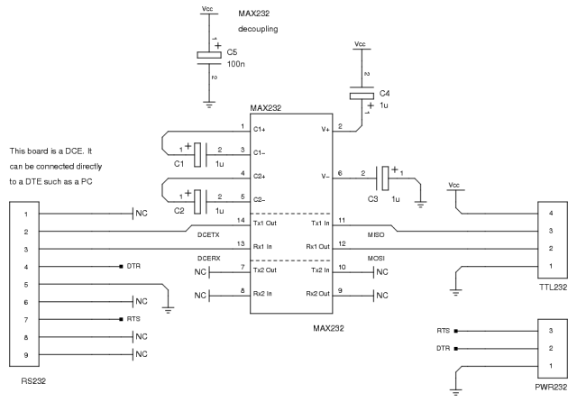
This project is available in two flavours:
..both of which have a 3-pin header for getting parasitic power over RS232.
The DCE version is laid out on veroboard and re-uses an RS232 header cable from an old PC:
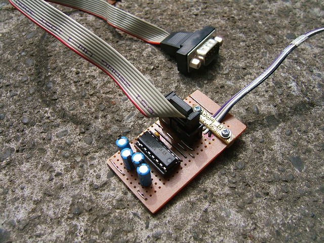
The fragment of etched circuit board on the photo above is not part of the circuit. It’s just reclaimed board holding that cable down so that no pressure is exterted on the soldered joints where the cable meets the board.
The archive includes gEDA source files for the schematics and either single-sided PCB ( for connection to a DTE) or veroboard ( for connection to a DCE) layouts.